Commodore 128 Tips & Tricks
VIC-IIe
GRAPHIC command
Commodore 128 BASIC V7 GRAPHIC command allocates RAM for bitmap at $2000 - $3F40 (8192-16191) and relocates BASIC program from $1C00 to $4000.
So, for saving bitmap and color data you can use:
A$="filename"
BSAVE ""+A$+".BMP",B15,P8192 TO P16181:REM BITMAP DATA
BSAVE ""+A$+".COL",B15,P7168 TO P8167:REM COLOR DATA
to load:
BLOAD ""+A$+".BMP"
BLOAD ""+A$+".COL"
It's for Hi-Res mode, where:
$1C00 - $1FE7 = color data
$2000 - $3F40 = bitmap data
Format of Koala painter:
Features (see Explanations for details):
- 1 Bitmap, 1 Screen-RAM, Color-RAM
- Multicolor pixels
Memory-Structure ($6000-$8711, 10001 Bytes, 40 Blocks):
$6000 - $7F3F: Bitmap -> $2000 - $3F40
$7F40 - $8327: Screen-RAM -> $1C00 - $1FE7
$8328 - $870F: Color-RAM -> $D800 - $DBE7
$8710 : Background-Color -> $D021
Performing GRAPHIC in assembler:
CMP #$9C
BNE $6B69
JSR $A022 ; Move Basic to $1C01
JSR $0380 ; CHRGET
LDA #$00
STA $D8 ; Graphics mode code (BIT765: 000=0, 001=1, 011=2, 101=3, 111=4)
RTS
or
POKEDEC("D8"),32:SYSDEC("6B5A")
$D8 is text/graphic mode flag
or
JSR $9F4F - allocates RAM for GRAPHIC
JSR $A022 - de-allocates RAM for GRAPHIC
flag $76 = 0 - not allocated / <>0 - allocated
MC-bitmap data for GRAPHIC3 command:
The C128 uses RAM $D800-$DBE7 (Color-RAM)
This RAM area is available twice!
The video matrix (in bitmap mode) holds two colors. One color in the high nibble and one color in low nibble. Note this comes from system RAM. For C128 example, $1c00 with hi-res or multi-color BASIC bitmap.
In multi-color bitmap, there are 4 colors: background (from VIC register at $d021), color 1, color 2, and color 3. Colors 1 and 2 come from system RAM / video matrix (like hi-res bitmap described above). Color 3 comes for "color RAM" at I/O region $d800-$dbe7.
In both C64 and C128, "color RAM" is a special chip that is only accessible to CPU when I/O is active (it is always accessible to VIC). For C64 you need a value like $35 or $37 in address $01; for C128 you need a value like $3e or $00 in address $ff00... if you want to access Color RAM.
Anyway, Color RAM holds bitmap color 3 (or text color). Normally you would just save $d800-$dbe7, but the C128 has TWO color banks! Although it is not well-documented, it is an awesome feature of the C128.
how can I explain... maybe an ASCII graph?
VIC
|
|
\ /
V
C0 / C1
^
/ \
|
|
CPU
In C64 mode, the CPU and VIC always access the same Color RAM (after all, the C64 only has one Color RAM).
In C128 mode you controll which Color RAM is used by the CPU and which one is used by VIC. Commodore's BASIC does this so nicely that most people don't even realize there are TWO banks of Color RAM.
Anyway in C128 mode, Color RAM access is controled by CPU I/O port $01. Bit 0 controls access by CPU, while bit 1 controls access by VIC. On power-up, both bits are set to 1. So you could call "Color RAM Bank 1" = "Text Color" and you could call "Color RAM Bank 0" = "MC Bitmap Color" (for lack of better name).
Umm, this is getting confusing to me... and I am writining it... let me see if I can simplify...
$01 / bit 0 = 0 (CPU access Color RAM 0 / mc-bitmap)
$01 / bit 0 = 1 (CPU access Color RAM 1 / text)
$01 / bit 1 = 0 (VIC access Color RAM 0 / mc-bitmap)
$01 / bit 1 = 1 (VIC access Color RAM 1 / text)
Normal value of "CPU Register $01" is $73; both CPU and VIC access Color RAM bank 1 / text.
In GRAPHIC 3/4 "CPU Register $01" is $75; the CPU will access Color RAM bank 1 (text) but VIC will access Color RAM bank 0 / mc_bitmap
Anyway, if you want to load/save a multi-color bitmap, you must be sure the CPU will access mc_bitmap Color RAM. The default IRQ routine will set "register" $01 bit 0 to "1" so normally CPU will only access text Color RAM. You need to disable IRQ and set "register" $01 bit 0 to "0" if you want to read/write/load/save the MC_Bitmap data at $d800~$dbe7.
I am sorry if this is confusing... Let me give a real-world example... If I want to save the bitmap Color RAM then I do this:
POKE 216,255:REM DISABLE KERNAL VIC CHANGES
POKE 1,PEEK(1)AND254:REM USE COLOR BANK 0 (MC-BITMAP)
BSAVE "FILENAME", B15, P55296 TO P56296
POKE 216,0:REM ENABLE KERNAL IRQ / VIC TEXT MODE
Notice after BSAVE that I do not POKE 1, x because the KERNAL IRQ will set value automatically after (re)enable with POKE 216,0. Maybe this is wrong? But it works for me.
At the moment, I can't think of a better description. So please ask questions and I will try to clarify this lousy description...
Robert Willie
Shadow registers of VIC-IIe
Have a look in "Mapping the C128", page 69, address 216/$D8. In order to be able to access the VIC's register directly you have to disable BASIC's screen editor IRQ routine and you do that by storing the value 255/$FF in this register.
From "Mapping the C128":
You can turn off the screen-setup portion of the screen editor IRQ routine by storing the value 255/$FF here. This gives you direct control over the VIC chip register settings, but disables BASIC'S ability to change display modes.
However you can't always take CBM at face value. While it is true BASIC's GRAPHIC command won't work after putting 255 into 216($d8), this is indirect.
$d8 controls the KERNAL/Editor portion of VIC-II IRQ. When you store 255 here, KERNAL/Editor will no longer update screen mode registers of VIC. This means BASIC's GRAPHIC command will not work.
However, this do not stop BASIC portion of VIC-II IRQ! You do this by clearing bit 1 of $A04. For example, POKE 2564, PEEK(2564) AND 254. Unless you do this, BASIC will continue to update SPRITE positions of VIC-II registers and also respond to COLLISIONs (both sprite and light-pen). Unfortunately, when you do this, BASIC updates to SID also stop working, so SOUND and PLAY will not work either.
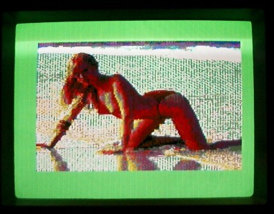
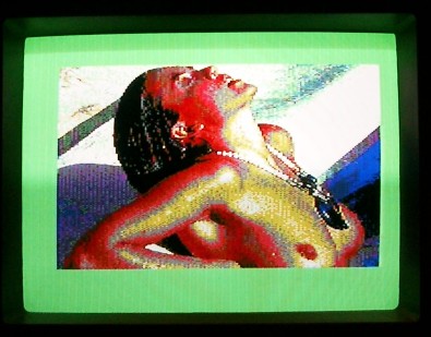
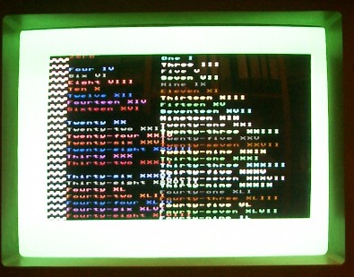
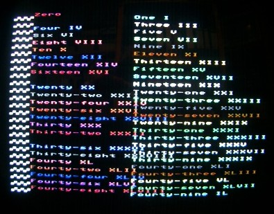
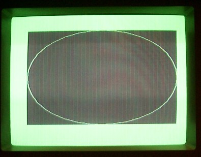
RIM = VIC II Real Interlace Mode (from WTE's webpage: C128.Net)
Robert Willie created a new interlace mode for the VIC IIe (MOS 8564/8566) in the Commodore 128. It is a real interlace mode (RIM). It is now possible to display 400 lines, which means to doubble the vertical resolution. The following pictures show screenshots of the demo programm, that is available for download from Roberts Hompage. Further Infos are available in the Forum of Commodore 128 Alive! Picture 04 evidences the possibility of the combination with FLI to a real interlace FLI (RIFLI). Unfortunately the brightness of the pictures is to high, so the clear resolution e.g. on the "e" is not visible anymore. Picture 08 and Picture 09 show the difference between activated and deactivated interlace mode.
For the real interlace mode a real Commodore128 is needed. Emulators (VICE) can't handle this new graphic mode until now. Also a C64 is refused to work with this high resolution graphic, because it presumes a VIC IIe.
Here are some screenshots:
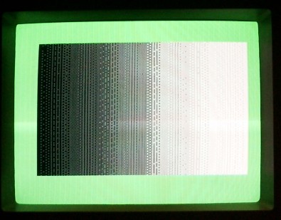
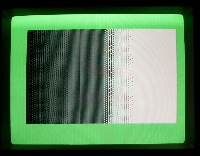
You can look at the dithering patterns:
http://www.efg2.com/Lab/Library/ImageProcessing/DHALF.TXT
And here's link to Commodore monitors info:
http://gona.atw.hu/Commodore/monitor/index.html
At download section you can find the RIM demo (be sure to test it on monitor which has interlaced function).
ABOUT GRAPHIC MODES USED ON C64, BUT CAN WORK ALSO ON C128!
source: www.c64.sk
HiRes Mode
HiRes mode generates a screen with resolution 320*200 pixels/16 colors. The screen is divided into 40*25 attribute cells. Each attribute cell is 8*8 pixels big.In this mode you can use maximum 2 colors in one attribute cell. It means that you can set color of background, and color of foreground (pixel color). This mode isn't very popular, although it's possible to paint very nice pictures in it. Even if nowadays artists use this mode they rarely use more than 2 colors in the picture. Probably they are lazy to play with these tricky attributes. Take for instance the following examples from more than 10 years old game. Even in-game graphic is in the high resolution.
MultiColor Mode
MultiColor mode generates the screen with resolution 160*200 pixels/16 colors. One pixel represents an area 2*1 pixels big. (it is fatter than hires pixel ;-) The screen is divided into 40*25 attribute cells. Each attribute cell is 4*8 pixel big. In this mode you can use maximum 4 colors in the attribute cell. Each pixel defined by 2 bites can have one of 4 different colors. One of colors is the background color. As you can observe from today's competitions and demos, almost nobody is able to paint nice pictures in this mode. Artists use MCI, FLI, IFLI, SHI, and SHIF modes instead. Though It's a bit demagogic saying that, ;-) because as you can notice from X-97 graphic compo, Bundy/WOW won competition with a MultiColor picture. Maybe it's an exception proving the rule, maybe just the sign that WOW has one of the best MultiColor artist of nowadays ;-).
FLI Mode
Flexible Line Interpretation mode generates same resolution as standard MultiColor mode - 160*200 pixels/16 colors. This technique allows to use more collors in the attribute cell. It allows artist to use the full palette of 16 colors in each 4*8 pixel big attribute cell. It's realized by a special routine, which by changing values in the VIC register $D011 causes that Bad Scan Line (In further text called Caroline*) is on each rasterline of visible screen. For those who don't know what a "Caroline" is: Caroline occur each 8th rasterline. It's the time when the graphical processor of C64 (VIC) is loading graphic data from memory. Bits 0-2 of the $d011 register (the VIC Control register) are used for the vertical smooth scrolling. Bad scan line happens.when the bits 0-2 of register $d011 are same as the bits 0-2 of register $d012 (raster-beam position register). In FLI, a Caroline happens on each raster line of the graphic screen. This means that VIC reads the values from attribute screens each rasterline, not only each 8th as it normally does. Then, when you change the $d018 register on each rasterline, in order to change an attribute screen, it is done. You can use 4 colors in each 8*1 pixels big attribute area. Special version of FLI is the HiRes FLI, which uses the same principles in HiRes mode. It allows graphician to use 2 colors (the background and foreground color) in 1*8 pixels big attribute area.
MCI Mode
Multi Color Interlace generates 320*200 pixel resolution. You can use 4 colors in each 8*8 points big attribute cell. This mode also gives the possibility of mixing two colors together, so there are 4 of theoretical amount of 128 colors. But how is it realised? Here is the answer:
This mode uses two MultiColor pictures (160*200/4 colors in 4*8 cell), each using its own attributes (except the color RAM at $d800, which is shared by both). These two MultiColor pictures alternates each frame, but one of them is shifted one point to the side. This causes visible effect of jerky movement from side to side. Fortunately, it also improves the fineness of C64 MultiColor mode, and gives painter larger color palette.
IFLI Mode
Interlaced Flexible Line Interpretation is the connection of two greatest ideas in history of C64 graphic modes. MultiColor Interlaced mode (MCI), and Flexible Line Interpretation mode (FLI). Interlaced FLI generates 320*200 dots resolution using 6 colors in each 8*1 points big attribute cell. This mode also gives the possibility of mixing two colors together, so it's possible to use theoretically 128 different colors. In this mode two FLI pictures alternates each frame, but one of them is shifted one point to the side. This causes a visible effect of jerky movement from side to side. Fortunately, it also improves the fineness of C64 FLI mode.
SuperHires - SH
SuperHires Interlace - SHI
Super Hires can theoretically generate pictures in resolution of 96*200 pixels/16 colors. Though standard size of the pictures is only 96*167 pixels. One 8*8 pixels big attribute area can contain 4 colors. 2 colors are same in the whole picture, and 2 can be set individually for each attribute area. (Background color, and foreground color, as in hires mode) Realisation is quite simple: Picture consists of 2 layers of multiplexed hires sprites. Hires sprite is 24*21 pixels big/1 color. Each layer consist of 4*8 hires sprites of the same color. Two layers give us 2 colors, and Hires picture lying behind them give us another two, which can be set separately for each 8*8 pixels big attribute area. Super Hires Interlace generates pictures 96*200 pixels big. It alternates two SuperHires pictures each frame. Like all interlacing modes, it can theoretically generate 128 colors palette. I think than now it's time to check the example picture. For me it was a shock when I saw this picture for the first time. Picture is painted by now inactive polish painter - Latifah. Believe it, or not - converted to non-interlaced mode it has 87 colors, and in one 8*8 pixels big attribute area it use 10 colors.
Super Hires FLI
Super Hires Interlace FLI
Super Hires FLI can generate pictures in resolution of 96*167 pixels/16 colors. Instead of HiRes picture, it uses the HiresFLI picture as a bacgkround layer. It can use 4 different colors in the 1*8 pixels big attribute area. 2 colors are same for the whole picture, the background, and foreground color can be set separately for each attribute area. Super Hires Interlace Fli alternates two SHF pictures each frame. An example picture, which uses SHIF mode was drawn by Deekay/Crest